A typical multi span cable ladder or cable tray installation behaves largely as a continuous beam.
Cable ladder support span calculation.
Hazardous voltages in electrical equipment can cause severe personal injury or death.
Unistrut s load testing is in accordance with cei iec 61537 2001.
610mm of a splice on straight sections and the span between supports should not exceed the length of tray.
And load figures inclusive of a safety factor of 1 7.
However in practice a run must contain joints and it can also never be of infinite length so it is important to appreciate how its characteristics vary from span to span and how these.
Temperature when installing cable ladders 20 ºc calculations temperature differential 40 ºc expansion of stainless steel for this temperature range 0 69 mm m expansion coupler gap when installing including safety factor 15 0 mm.
Using cable trays as walkways can cause personal injury and also damage cable tray and installed cables.
In the case of electrical products such as cable tray or ladder which are load rated in kilograms per metre the span is the distance between support points separate from the overall length of the tray or ladder itself.
The greater the number of spans the closer the similarity.
The span length from the support.
Do not use a cable tray as a walkway ladder or support for people.
In practical terms this covers continuous multi span installations evenly loaded along the length of and across the full width of the tray.
L intermediate span f deflection 1 100 of the intermediate span max s splice location.
To join two components together clamp or fix to walls ceilings or other supports covers and cable retainers associated supports bespoke supports for cable tray and cable ladder other than bs 6946 channel.
Cable tray is a mechanical support system for cables and raceways.
Supports should be placed within 24 in.
To ensure adequate support accessories should be supported locally.
Support of cable tray and ladder is typically.
Expansion splice plates.
The nema classes are based on cable loads of 50 75 and 100 per lineal foot.
Unistrut s load and deflection figures are in accordance with cei iec 61537 2001 with the characteristic deflection of unistrut cable ladder limited to span 100.
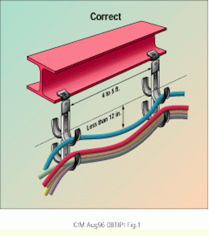
For support spans greater than 5 feet 1 5m cable loads must be evaluated to ensure that the span between the supports is suitable for the load the support and anchor must be evaluated separately.
Quick tray wire mesh cable tray fill table at 50.
The quick tray wire mesh cable tray fill table below shows the number of cables and the load in lbf lineal foot developed by typical 4 pair and 6 pair cable weighing 20 lb kft and 40 lb kft respectively while this table is a useful guide actual loads must be calculated using the cable specified.
6 cable ladder and cable tray systems including channel support systems and other associated supports definitions and abbreviations accessory component used for a supplementary function e g.

